Star news


NS073 Soldering kit - small heart with LEDs. DIY gift - LED heart How to make a heart for an LED strip
My grandmother's birthday was quickly approaching and I wanted to give her something nice and not too complicated. The fading LED effect never seems to go out of style, and grandmas always love hearts, so I decided to combine the two.
The concept behind this little birthday gift is to create a small heart using LEDs placed on a heart drawn on a circuit board. A microcontroller is used to control the LEDs. PWM LED control allows for longer battery life and precise control over the brightness of each LED.
Purpose and overview of this project
The goal of this project is to create a PCB with LEDs connected to a microcontroller. The LEDs must be controlled by a microcontroller so that an individual brightness level can be set for each LED. In this case, there should be 6 operating modes:
All LEDs go off and on.
- The LEDs go out in waves from bottom to top.
- The LEDs go out in waves from right to left.
- The LEDs light up line by line.
- The LED columns light up.
To achieve this goal, I used 16pcs of 5mm red LEDs for the heart and a PIC 18F252 microcontroller for control. Some other elements are also needed. Their list is presented below.
Elements
PIC18F252
Programmer for PIC PICKit2
7805 Stabilizer +5V
16x Red 5mm LED
16x 100ohm resistor
Resistor 10kOhm
Quartz 20MHz
Tumblr
2x capacitor 1uF
Capacitor 0.1uF
2x capacitor 15pF (22pF suitable)
+9V battery holder
4x Rack
Cork base
Foil PCB
Ferric chloride (Etching solution)
Glossy paper
Laser printer
Solder
Soldering iron
Detailed list of items
There are too many elements in this project to describe them all in detail, but I will provide additional information about the main elements used.
PIC18F252
This is a small microcontroller (processor + memory). It will control each LED individually, which is the goal of this project. PIC microcontrollers are very versatile, and in fact the PIC 18F252 has many more functions than we use for LED dimming. It's too bad we don't use them all.
Programmer for PIC PICKit2
In order to load the program (firmware) into the PIC, a programmer is needed. PICKit2 is a programmer/debugger and one of the most popular PIC programmers.
16xred 5mm LED
16 LEDs are used to create the heart. It's not a lot of LEDs, and the heart looks a little 'pixelated', but I'm okay with that. You can use more LEDs if you want.
Quartz 20MHz
Quartz is not that important in this project. You can use quartz at 4 MHz, 1 MHz or 40 MHz. I just found the 20 MHz quartz first in my set of elements.
Foil PCB and ferric chloride
Since I want to make a printed circuit board, I will need double-sided foil PCB and ferric chloride for etching. It is used to make the board.
Circuit overview
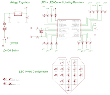
The circuitry for this project is not that complicated and basically consists of LEDs connected via current limiting resistors to a PIC. It may seem that I chose the pin to connect each LED in a random order, but this is not the case. This is made for more convenient tracing of the printed circuit board.
Features of the scheme
+5V stabilizer and On/Off switch.
A 7805 linear regulator is used to step down the +9V battery to +5V to power the PIC. A toggle switch installed between battery negative and GND, when closed, allows current to flow through the circuit, allowing the device to be turned on and off.
PIC microcontroller and 100 Ohm resistors
The PIC common pins PORTA, PORTB, and PORTC are used to connect each LED so as to gain maximum software control over it. 100 Ohm current limiting resistors between the PIC pins and the LEDs protect the PIC and LEDs from burning out if the current on the microcontroller and LED pins is too high.
Heart shaped LEDs
All LEDs were given a numerical designation and their position in the heart was indicated to avoid confusion. Also, matching software and hardware greatly simplifies program writing.
Board overview
The board is divided into two parts: the left part is reserved for LEDs and the heart, and the right part is for all electronics. Dividing the board into two parts gives symmetry between the working part and the part with the heart.
Features of the board

PIC 18F252 and current limiting resistors
As you can see, the heart, PIC and resistors are installed on the second side of the board. The resistors are positioned so that the paths to the LEDs are straight and simple.
Heart shaped LEDs
The board shows a rough arrangement of LEDs in the shape of a heart. The heart will look better against the red background on the board. Also on the second side of the board I made the inscriptions “Happy Birthday” and “91” (my grandmother’s age!).
4 Racks
I drilled 4 holes in the corners of the board for the stands. Their location can be seen on the top and bottom layers.
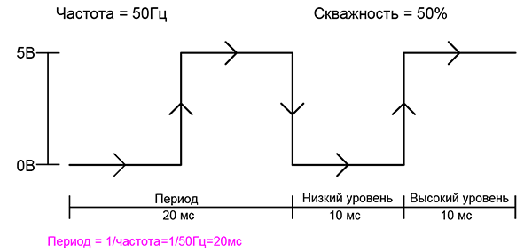
PWM operating principle
To control the brightness of the LED we will use a PWM signal. A PWM signal is a pulse width modulated signal. Any PWM signal has three main parameters:
Frequency
Duty factor
Amplitude
These three parameters show us the type of PWM signal, which allows us to predict how it will affect our system. Below are several examples of PWM signals and their parameters.
PWM examples

The type of PWM signal is shown in the figure above. We will use a frequency range of 60-120Hz, with an amplitude of +5V (our system operates on +5V). The duty cycle will fluctuate between 0% (LED turned off completely) and 100% (LED turned on at full power).
Turning on the PWM LED
What happens when we send a PWM signal to an LED? The LED lights up for a short time equal to the duration of the pulse. Since we will be using a frequency of 60-120Hz, the LED will appear to be constantly on due to the persistence effect. The brightness of the LED will be controlled by changing the duty cycle percentage. The animation below gives an idea of the effect of different PWM signals on an LED.
Now we know a simple way to adjust the brightness of the LEDs and turn them off. Let's see how we are going to apply this method in different modes of the heart.
Operating modes
For the purposes of the project, we specified 6 operating modes. Let's look at them again in more detail so that it is clear in what mode the LEDs work.
In this mode, only one LED is lit at a time. All LEDs light up alternately, each LED lights up once. Below is an animation of this mode.
All LEDs go off and on.
In this mode, all LEDs fade smoothly and go out at the same speed five times. Below is an animation of this mode.
The LEDs go out in waves from bottom to top.
In this mode, the LEDs turn off from bottom to top, creating a wave-like effect. Below is an animation of this mode.
The LEDs fade out in waves from right to left.
In this mode, the LEDs turn off from right to left, again creating a wave-like effect. Below is an animation of this mode.
The LEDs light up line by line.
In this mode, the LEDs light up line by line. Only one line lights up at a time, all others are turned off at this moment. Below is an animation of this mode.
The LED columns light up.
In this mode, columns of LEDs light up. Only one column lights up at a time, all others are turned off at this time. Below is an animation of this mode.
After all 6 modes are completed, the program returns to 1 and everything starts from the beginning. It's endless!
Hardware
The manufacture of the hardware of the device is divided into two parts: the first part shows the manufacture of the printed circuit board, and the second part shows its assembly.
PCB manufacturing
To make a double-sided PCB, we will use the LUT method, which involves printing the board design on glossy paper and smoothing it onto the PCB. From the photographs below you can understand how I made a printed circuit board from an Eagle file.

To begin with, the top and bottom layers of the board are printed on glossy paper using a laser printer.

Using a hot iron, transfer the design of the top and bottom layers onto the PCB by “ironing”.

As you can see in the photo above, we transferred the toner to the board.
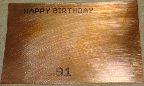
Most of the copper on the top side is etched away, leaving only the areas protected by the toner (the inscription).

After etching the board, it is clear that all the copper, except that which was protected by the toner, was etched away.

The same thing happens with the bottom side of the board.

By removing the toner you'll get a better idea of how the copper was protected and you'll see the circuit board.

The top side also looks much better after removing the toner.

I hope you have a drill press. If not, then a regular drill will do to make the holes.

Once the holes are drilled, use a sander or any other means to round the edges of the board. This makes the board much more comfortable to use and it doesn't scratch anything.
Circuit assembly
We have just made a printed circuit board, and now we can start assembling. Nan will need a soldering iron and solder.
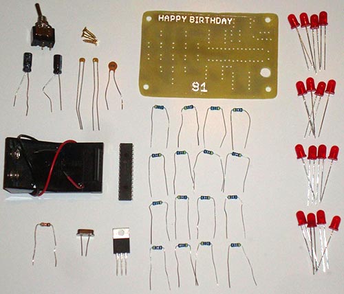
All elements are required to assemble a printed circuit board. All necessary elements are shown in the photo below.
To begin, draw a heart with a red marker. It gives a beautiful look and shows that it really is a heart.
Once the heart is drawn, start soldering the LEDs.

Once the LEDs are soldered, it's time to solder the resistors. I would like to add that it is better to solder small elements first, it is easier to do it better.
Once the resistors are soldered, only a few elements remain: a microcontroller, a few capacitors, a stabilizer and other small parts. Solder them.

Once all the parts are soldered to the board, there are a few things left to do. Place the board on the base and attach the +9V battery holder to it.
I used a piece of wood with rounded edges as the base. You can use plastic or something else rectangular and strong.

After all this hard work, it's time to write the program.
Result and notes
After all the hard work, we want to see the result. The video below shows the manufacture of the board and how the firmware controller controls the LEDs in 6 modes, which were discussed earlier.
Looks good, doesn't it? The main disadvantage is that my camera operates at a different frequency than our eye, so there is flicker in the video. But that's ok, it still looks amazing to the human eye and you can rest assured that this project works damn well.
Review of LED heart with PWM attenuation
This article is a summation of my boredom and the need for a birthday gift for my grandmother. When these two things collide, you end up with a board with an LED heart that operates in different modes. The PIC microcontroller in this project did the job for us, as did the PCB etching process, which I have used several times already. I had concerns that the +9V battery might not be enough, but the project works great.
So what's now?
If you want to make a device better than mine, then you have a lot of options. To begin with, you can increase the size of the heart. This will require a different control method, because... The number of PIC pins is limited. An I/O port expander will allow you to do this, such as a serial to parallel converter. Use your imagination and come up with ways to improve this project.
Conclusion
The main goal of this project was to create an LED heart operating in different modes mentioned above and this goal was achieved, as proven in the Result section. I hope this article inspired you to make a cool gadget for your grandma for her birthday. Good luck!
List of radioelements
| Designation | Type | Denomination | Quantity | Note | Shop | My notepad |
|---|---|---|---|---|---|---|
| IC1 | MK PIC 8-bit | PIC18F2520 | 1 | To notepad | ||
| IC2 | Linear regulator | LM7805 | 1 | To notepad | ||
| C1, C2 | Electrolytic capacitor | 1 µF | 2 | To notepad | ||
| C3 | Capacitor | 0.1 µF | 1 | To notepad | ||
| C4, C5 | Capacitor | 15 pF | 2 |
- This is a square pulse generator. The diagram shows a symmetrical multivibrator; it is a self-oscillator (that is, the generation of pulses begins from the moment the voltage is applied and then occurs automatically). It is symmetrical due to the same resistances of resistors R1 and R4, R2 and R3, capacitances C1 and C2, parameters of transistors TR1 and TR2.
Pulse duration such multivibrator regulated by the values of C1, R2 and C2, R3. It is also calculated using the formula T=(3…5)*C1*R2 or T=(3…5)*C2*R3, depending on which transistor the signal is taken from. Resistors R1 and R4 regulate the current through the load.
There are many uses for this device, here are just two of them:
LED switch
Generator for tweeter
This animation shows an example of how a multivibrator works; LEDs are used as a load. The capacitors are electrolytic, their minus goes to the 27 KOhm resistors.
I used this circuit as a simulation running lights effect. We find a suitable housing and drill holes for the LEDs.
And finally, by increasing the number of LEDs in the circuit and alternating them, we get the following homemade product. I connected 8 LEDs in parallel, took 300 Ohm resistors and powered them with a Krona battery (9 Volts).


I don’t pretend to be a new idea or execution, but it may be useful to someone. Actually, this device was made for my wife for her wedding anniversary, although you can quite easily repurpose it for other holidays.
The electrical circuit diagram was found on the Internet and was safely lost there. That's why it won't happen. Yes, in principle, it itself is not needed because This device is a logical continuation of the first attempts to light LEDs. The idea itself was to please my wife and prove to her that it’s not in vain that I sit with a soldering iron in the evenings.

Signet in Sprint Layout
As you can see from the printed circuit board there is nothing special about it:
- Atmega8-tqfp32
- Resume for 100k
- Conder 0.1 µF
- 22 smd leds
- 22 smd shortcut
Regarding LEDs and resistors, perhaps choose them so that they do not exceed the threshold voltage value of +5V. I took super bright ones at 3V, current 20 mA, respectively, the cutters were 120 ohms.
Without thinking too much, there are a bunch of online calculators.
There is no connector for ISP programming in the usual sense. Stupid wiring. By the way, everything is signed there for convenience. I think it is not advisable to present the process of “LOOTING” the board and explaining the technology here, because those who can and know will understand, and those who don’t have Google to help them.

Immediately soldered scarf.
And of course, as in the Russian joke about an airplane, “Now roughly handle it with a file.” Regarding the code, there will only be a firmware file without source codes, because this is a standard nogodryg.
I almost forgot the video. I apologize for the quality; I had it on hand.
I guess that's all. Project file:
About Fuse, we leave it at the factory. Happy repeat everyone.
I don’t pretend to be a new idea or execution, but it may be useful to someone. Actually, this device was made for my wife for her wedding anniversary, although you can quite easily repurpose it for other holidays.
Photo of the device
The electrical circuit diagram was found on the Internet and was safely lost there. That's why it won't happen. Yes, in principle, it itself is not needed because This device is a logical continuation of the first attempts to light LEDs. The idea itself was to please my wife and prove to her that it’s not in vain that I sit with a soldering iron in the evenings.

Signet in Sprint Layout
As you can see from the printed circuit board, there is nothing special in it: Atmega8-tqfp32, 100k rezuk, 0.1 uF conder, 22 smd LEDs and 22 smd rezuk.
Regarding LEDs and resistors, perhaps choose them so that they do not exceed the threshold voltage value of +5V. I took super bright ones at 3V, current 20 mA, respectively, the cutters were 120 ohms.
There is no connector for ISP programming in the usual sense. Stupid wiring. By the way, everything is signed there for convenience. I think it is not advisable to present the process of “LOOTING” the board and explaining the technology here, because those who can and know will understand, and those who don’t have Google to help them.

Immediately soldered scarf.
And of course, as in the Russian joke about an airplane, “Now roughly handle it with a file.” I’m just learning about soldering, so don’t criticize too much, and in general this is one of my first projects. Regarding the code, I’m also learning so there will only be a firmware file without source codes (otherwise I think they’ll get stuck).
I almost forgot the video. I apologize for the quality - what was on hand. I guess that's all. Project file: . About Fuse - we leave it at the factory.
Source: we.easyelectronics.ru
| This diagram is also often viewed: |
The design is easiest to do on a breadboard using 10 red LEDs, a decimal counter chip like CD4017 and the legendary 555 Timer in self-oscillating mode and some wiring elements. The circuit is simplified as much as possible and should start immediately when you turn it on for the first time, unless, of course, you mess up anything and all components are in working order.

The pulse generator on the NE555 timer chip operates in a self-oscillating mode, generating a rectangular pulse sequence; the pulse repetition rate is set by the nominal value of the resistor R4 and the capacitance of the capacitor C1. Visually, it is clearly visible that by changing the resistance R4 we change the speed of the LEDs.

It is advisable to place the finished device in a beautiful box, leaving only the LEDs and the voltage supply button outside. You can use almost any battery with a voltage of 5-12 volts. For example, Krona or 2 AA elements connected in series.
I spotted this interesting project on one amateur radio blog: http://blog.xelfaer.ru/?p=606. Unfortunately, I didn’t repeat it myself, but I think I’ll definitely use this in practice, but only on a different microcontroller. For this circuit we need: ATmega8 microcontroller (necessarily in a TQFP package); 22 SMD red LEDs; 22 SMD resistors 620 Ohm; SMD resistor 10 kOhm; SMD capacitor 0.1 µF. All radio components size 0805